
| |||
|---|---|---|---|
|
|
|
||
- SystemVerilog
- Verification
- Constructs
- Interface
- OOPS
- Randomization
- Functional Coverage
- Assertion
- DPI
- UVM Tutorial
- VMM Tutorial
- OVM Tutorial
- Easy Labs : SV
- Easy Labs : UVM
- Easy Labs : OVM
- Easy Labs : VMM
- AVM Switch TB
- VMM Ethernet sample
- Verilog
- Verification
- Verilog Switch TB
- Basic Constructs
- OpenVera
- Constructs
- Switch TB
- RVM Switch TB
- RVM Ethernet sample
- Specman E
- Interview Questions

Introduction to Ethernet Frames : Part - 1
This tutorial is divided into two parts. Part-1 will be on Ethernet Frames and Part-2 will be on Simple Ethernet Testplan.
For Part-2 , Click
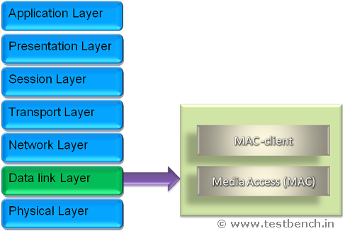
1.Ethernet Protocol Layer
The Ethernet protocol basically implements the bottom two layers of the Open Systems Interconnection (OSI) 7-layer model, i.e., the data link and physical sub layers. Following Figure depicts the typical Ethernet protocol stack and the relationship to the OSI model.
2.Ethernet Frame Structure
The following illustrates the format of an Ethernet frame as defined in the original IEEE 802.3 standard
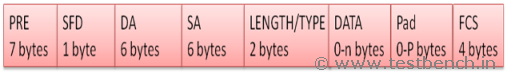
Preamble

A sequence of 56 bits having alternating 1 and 0 values that are used for synchronization. They serve to give components in the network time to detect the presence of a signal, and read it before the frame data arrives.
Destination MAC Address

The Destination MAC Address field addresses destination stations. This may addresses single or multiple stations.
Destination Address (6bytes) of all 1 bits refers to all stations on the LAN and is called a "Broadcast address".
Start Frame Delimiter

Sequence of 8 bits having the bit configuration 10101011 indicates the start of the frame.
Source MAC Address

The Source MAC Address addresses the station at which it originated. The 802.3 standard permits these address fields to be either 2-bytes or 6-bytes in length.
Length/Type (2bytes)

If the value of this field is less than or equal to 1500, then the Length/Type field indicates the number of bytes in the subsequent MAC Client Data field. If the value of this field is greater than or equal to 1536, then the Length/Type field indicates the nature of the MAC client protocol (protocol type)
MAC Client Data

This field contains the actual data transferred from the source station to the destination station or stations. The maximum size of this field is 1500 bytes. If the size of this field is less than 46 bytes, then use of the subsequent "Pad" field is necessary to bring the frame size up to the minimum length.
Pad

If necessary, extra data bytes are appended in this field to bring the frame length up to its minimum size. A minimum Ethernet frame size is 64 bytes from Destination MAC Address(DA) field through the Frame Check Sequence(FCS).
Frame Check Sequence (FCS)

This field contains a 4-byte Cyclic Redundancy Check (CRC) value used for error checking.
When a source station assembles a MAC frame, it calculates a CRC checksum on all the bits in the frame from Destination MAC Address (DA) to the Pad fields (that is, all fields except the preamble, start frame delimiter, and frame check sequence).
The source station stores this CRC value in this field and transmits it as part of the frame. When the frame is received at destination station, it calculates CRC of received data and compares it with FCS. If it does not match then destination station assumes an error occurred during transmission and discards the frame.
The original Ethernet standards defined the minimum frame size as 64-bytes and the maximum as 1518-bytes. These numbers include all bytes from the Destination MAC Address field through the Frame Check Sequence field. The Preamble and Start Frame Delimiter fields are not included when quoting the size of a frame. The IEEE 802.3ac standard released in 1998 extended the maximum allowable frame size to 1522-bytes to allow a "VLAN tag" to be inserted into the Ethernet frame format.
Interframe Gap
Ethernet devices must allow a minimum idle period between transmission of frames known as the interframe gap (IFG) or interpacket gap (IPG). It provides the time for devices to recover and prepare to receive next frame. The minimum interframe gap is 96 bit times.
3.Frame Format Extensions
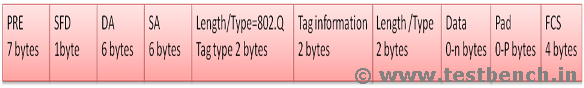
VLAN Tagging
The VLAN protocol permits insertion of an identifier, or "tag", into the Ethernet frame format to identify the VLAN to which the frame belongs. It allows frames from stations to be assigned to logical groups. This provides various benefits such as easing network administration, allowing formation of work groups, enhancing network security, and providing a means of limiting broadcast domains, The 802.3ac standard defines only the implementation details of the VLAN protocol those are specific to Ethernet. The 4-byte VLAN tag is inserted into the Ethernet frame between the Source MAC Address field and the Length/Type field. The first 2-bytes of the VLAN tag consist of the "802.1Q Tag Type" and are always set to a value of 0x8100. The 0x8100 value is actually a reserved Length/Type field assignment that indicates the presence of the VLAN tag, and signals that the traditional Length/Type field can be found at an offset of 4-bytes further into the frame.
The last 2-bytes of the VLAN tag contain the following information
 The first 3-bits are a User Priority Field that may be used to
Assign a priority level to the Ethernet frame.
The next 1-bit is a Canonical Format Indicator (CFI) used in Ethernet frames to indicate the presence of a Routing Information Field (RIF).
The first 3-bits are a User Priority Field that may be used to
Assign a priority level to the Ethernet frame.
The next 1-bit is a Canonical Format Indicator (CFI) used in Ethernet frames to indicate the presence of a Routing Information Field (RIF).
The last 12-bits are the VLAN Identifier (VID) which uniquely identifies the VLAN to which the Ethernet frame belongs.
JUMBO Frames
JUMBO frames are introduced in order to Increase the maximum size of the MAC Client Data field, larger frames would provide more efficient use of the network Bandwidth while reducing the number of frames that have to be processed.
JUMBO frames has the capacity to carry bytes from 64bytes (min size) to 9000bytes (max size)
The 8870 value is actually a reserved Length/Type field assignment that indicates frame as JUMBO.
PAUSE Frames
Flow control operation known as "PAUSE" frames are included in 10GBE as it supports the full duplex mode.
The 8808 value is actually a reserved Length/Type field assignment that indicates frame as PAUSE. Length/Type field is followed by 2 bytes of MAC control Opcode (00-01) and 2bytes of MAC control Parameter (timer=00-00toFF-FF) with a unique DA (01-80-c2-00-00-01) in MAC DA field
PAUSE frame considers 64bytes as Minimum size and 1518bytes as Maximum size for Normal frame and 1522bytes when tagged.
Transmitter Mac should not transmit the frames once it receives Pause frames from receiver until the time duration specified in the Pause timer
Transmitter Mac should reset/replace the current pause timer with newly arrived pause time when a Pause frame arrives from receiver before the current Pause time expires.
About the authors:
Bhavani shankar is VLSI engineer at Kacper Technologies Pvt. Ltd. Bhavani shankar is an master in VLSI-CAD from Manipal Centre for Information Science, Manipal.
Gopi Krishna He is the Author of testbench.in.
Report a Bug or Comment on This section - Your input is what keeps Testbench.in improving with time!