
| |||
|---|---|---|---|
|
|
|
||

SPECIFICATION
Switch Specification:
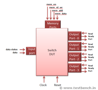
This is a simple switch. Switch is a packet based protocol. Switch drives the incoming packet which comes from the input port to output ports based on the address contained in the packet.
The switch has a one input port from which the packet enters. It has four output ports where the packet is driven out.
Packet Format:
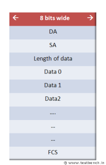
Packet contains 3 parts. They are Header, data and frame check sequence.
Packet width is 8 bits and the length of the packet can be between 4 bytes to 259 bytes.
(S)Packet header:
Packet header contains three fields DA, SA and length.
 DA: Destination address of the packet is of 8 bits. The switch drives the packet to respective ports based on this destination address of the packets. Each output port has 8-bit unique port address. If the destination address of the packet matches the port address, then switch drives the packet to the output port.
SA: Source address of the packet from where it originate. It is 8 bits.
Length: Length of the data is of 8 bits and from 0 to 255. Length is measured in terms of bytes.
If Length = 0, it means data length is 0 bytes
If Length = 1, it means data length is 1 bytes
If Length = 2, it means data length is 2 bytes
If Length = 255, it means data length is 255 bytes
Data: Data should be in terms of bytes and can take anything.
FCS: Frame check sequence
This field contains the security check of the packet. It is calculated over the header and data.
Configuration:
Switch has four output ports. These output ports address have to be configured to a unique address. Switch matches the DA field of the packet with this configured port address and sends the packet on to that port. Switch contains a memory. This memory has 4 locations, each can store 8 bits. To configure the switch port address, memory write operation has to be done using memory interface. Memory address (0,1,2,3) contains the address of port(0,1,2,3) respectively.
Interface Specification:
The Switch has one input Interface, from where the packet enters and 4 output interfaces from where the packet comes out and one memory interface, through the port address can be configured. Switch also has a clock and asynchronous reset signal.
(S)MEMORY INTERFACE:
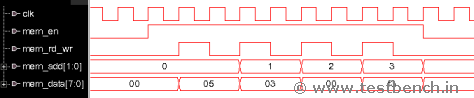
Through memory interfaced output port address are configured. It accepts 8 bit data to be written to memory. It has 8 bit address inputs. Address 0,1,2,3 contains the address of the port 0,1,2,3 respectively.
There are 4 input signals to memory interface. They are
input mem_en;
input mem_rd_wr;
input [1:0] mem_add;
input [7:0] mem_data;
All the signals are active high and are synchronous to the positive edge of clock signal.
To configure a port address,
1. Assert the mem_en signal.
2. Asser the mem_rd_wr signal.
3. Drive the port number (0 or 1 or 2 or 3) on the mem_add signal
4. Drive the 8 bit port address on to mem_data signal.
(S)INPUT PORT
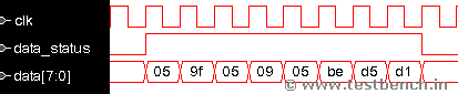
Packets are sent into the switch using input port.
All the signals are active high and are synchronous to the positive edge of clock signal.
input port has 2 input signals. They are
input [7:0] data;
input data_status;
To send the packet in to switch,
1. Assert the data_status signal.
2. Send the packet on the data signal byte by byte.
3. After sending all the data bytes, deassert the data_status signal.
4. There should be at least 3 clock cycles difference between packets.
(S)OUTPUT PORT
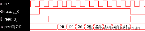
Switch sends the packets out using the output ports. There are 4 ports, each having data, ready and read signals. All the signals are active high and are synchronous to the positive edge of clock signal.
Signal list is
output [7:0] port0;
output [7:0] port1;
output [7:0] port2;
output [7:0] port3;
output ready_0;
output ready_1;
output ready_2;
output ready_3;
input read_0;
input read_1;
input read_2;
input read_3;
When the data is ready to be sent out from the port, switch asserts ready_* signal high indicating that data is ready to be sent.
If the read_* signal is asserted, when ready_* is high, then the data comes out of the port_* signal after one clock cycle.
(S)RTL code:
RTL code is attached with the tar files. From the Phase 1, you can download the tar files.
Switch Specification:
This is a simple switch. Switch is a packet based protocol. Switch drives the incoming packet which comes from the input port to output ports based on the address contained in the packet.
The switch has a one input port from which the packet enters. It has four output ports where the packet is driven out.
Packet Format:
Packet contains 3 parts. They are Header, data and frame check sequence.
Packet width is 8 bits and the length of the packet can be between 4 bytes to 259 bytes.
(S)Packet header:
Packet header contains three fields DA, SA and length.
DA: Destination address of the packet is of 8 bits. The switch drives the packet to respective ports based on this destination address of the packets. Each output port has 8-bit unique port address. If the destination address of the packet matches the port address, then switch drives the packet to the output port.
SA: Source address of the packet from where it originate. It is 8 bits.
Length: Length of the data is of 8 bits and from 0 to 255. Length is measured in terms of bytes.
If Length = 0, it means data length is 0 bytes
If Length = 1, it means data length is 1 bytes
If Length = 2, it means data length is 2 bytes
If Length = 255, it means data length is 255 bytes
Data: Data should be in terms of bytes and can take anything.
FCS: Frame check sequence
This field contains the security check of the packet. It is calculated over the header and data.
Configuration:
Switch has four output ports. These output ports address have to be configured to a unique address. Switch matches the DA field of the packet with this configured port address and sends the packet on to that port. Switch contains a memory. This memory has 4 locations, each can store 8 bits. To configure the switch port address, memory write operation has to be done using memory interface. Memory address (0,1,2,3) contains the address of port(0,1,2,3) respectively.
Interface Specification:
The Switch has one input Interface, from where the packet enters and 4 output interfaces from where the packet comes out and one memory interface, through the port address can be configured. Switch also has a clock and asynchronous reset signal.
(S)MEMORY INTERFACE:
Through memory interfaced output port address are configured. It accepts 8 bit data to be written to memory. It has 8 bit address inputs. Address 0,1,2,3 contains the address of the port 0,1,2,3 respectively.
There are 4 input signals to memory interface. They are
input mem_en;
input mem_rd_wr;
input [1:0] mem_add;
input [7:0] mem_data;
All the signals are active high and are synchronous to the positive edge of clock signal.
To configure a port address,
1. Assert the mem_en signal.
2. Asser the mem_rd_wr signal.
3. Drive the port number (0 or 1 or 2 or 3) on the mem_add signal
4. Drive the 8 bit port address on to mem_data signal.
(S)INPUT PORT
Packets are sent into the switch using input port.
All the signals are active high and are synchronous to the positive edge of clock signal.
input port has 2 input signals. They are
input [7:0] data;
input data_status;
To send the packet in to switch,
1. Assert the data_status signal.
2. Send the packet on the data signal byte by byte.
3. After sending all the data bytes, deassert the data_status signal.
4. There should be at least 3 clock cycles difference between packets.
(S)OUTPUT PORT
Switch sends the packets out using the output ports. There are 4 ports, each having data, ready and read signals. All the signals are active high and are synchronous to the positive edge of clock signal.
Signal list is
output [7:0] port0;
output [7:0] port1;
output [7:0] port2;
output [7:0] port3;
output ready_0;
output ready_1;
output ready_2;
output ready_3;
input read_0;
input read_1;
input read_2;
input read_3;
When the data is ready to be sent out from the port, switch asserts ready_* signal high indicating that data is ready to be sent.
If the read_* signal is asserted, when ready_* is high, then the data comes out of the port_* signal after one clock cycle.
(S)RTL code:
RTL code is attached with the tar files. From the Phase 1, you can download the tar files.
Index
Introduction
Specification
Verification Plan
Phase 1 Top
Phase 2 Environment
Phase 3 Reset
Phase 4 Packet
Phase 5 Generator
Phase 6 Driver
Phase 7 Receiver
Phase 8 Scoreboard
Phase 9 Coverage
Report a Bug or Comment on This section - Your input is what keeps Testbench.in improving with time!

Introduction
Specification
Verification Plan
Phase 1 Top
Phase 2 Environment
Phase 3 Reset
Phase 4 Packet
Phase 5 Generator
Phase 6 Driver
Phase 7 Receiver
Phase 8 Scoreboard
Phase 9 Coverage
Report a Bug or Comment on This section - Your input is what keeps Testbench.in improving with time!