
| |||
|---|---|---|---|
|
|
|
||

VERIFICATION PLAN
The Verification Plan is the focal point for defining exactly what needs to be tested, and drives the coverage criteria. Success of a verification project relies heavily on the completeness and accurate implementation of a verification plan. A good plan contains detailed goals using measurable metrics, along with optimal resource usage and realistic schedule estimates. Verification plan gives an opportunity to present and review the strategy for functional verification before the verification engineer have gone into detail to implement it. It also establishes proper communication. Just imagine how it would be working with a multisite project and you have a query for which you have to wait till the next day to see the answer in email and they just call you while you are in sleep. It also gives an idea about the areas that are going to be difficult to verify for taking necessary steps. It is used to determine the progress and completion of the verification phase of verification. Verification Planning should start early with system/architecture evaluation phase. Once the functional spec is given to the verification team, they will start its development.
A verification plan could come in many forms, such as a spreadsheet, a document or a simple text file. Templates are good if continually used in your company as it makes common interface for information, reviewer know where to look for certain information even in a huge document that he wants to know at this moment, because different reviewers want different infomation in different moments.
Generally Verification plan development is divided in two steps: What to verify and How to verify?
Step one: What to Verify?
list of clearly defined features-to-verify. This is called feature extraction phase.
Step two: How to Verify?
After defining what exactly need to be verified, define how to verify them.
Verification Plan Contains The Following:
 Overview
Resources, Budget and Schedule
Verification Environment
System Verilog Verification Flow
Feature Extraction
Stimulus Generation Plan
Checker Plan
Coverage Plan
Details of reusable components
Overview
This section contains description of the project, what specification is followed, what languages and methodology are used. Information related to the HW blocks, SW blocks and HW/SW interaction is outlined.
Feature Extraction
This section contains list of all the features to be verified. Generally each feature is associated with
1. Unique Name Id
2. Description
3. Expected result
4. Pointer to the specification
5. priority.
The "Unique name ID" should be descriptive in nature to understand the nature of the feature and should be unique. For example, <module name>_<sub module>_<feature number>_<feature name>
Some points on how extraction the features:
Read the MRD, System Specification, Macro and Micro Hardware Specification.
Go through the designer notes/presentations.
Annotate each line/paragraph specifying a functional item e.g., read/write a register
Annotate each line/paragraph specifying a multiple-functional items e.g., steps required to set and cause an interrupt .
Identify all RTL configurations
Identify interfaces and related protocols across interface.
Identify standards compliance requirements, list corner cases.
Create a list of illegal scenarios to verify.
Create a list of exceptions to verify.
Create a list of operation sequences to verify e.g., interrupt followed by breakpoint etc.
Create a list of things to try and break the machine.
Take advantage of existing plans.
Use points from compliance checklist for standard protocols.
Get information about the Common tests for all chips.
Get review by a number of people, usually very experienced engineers. Better if you get reviewed by Architects, micro Architects, Leads, verification engineers, RTL Designers, software designers, marketing team and other team members.
Resources, Budget And Schedule
This section contains details of man power required and schedule for each phase of the verification. Information about the tools which are used for simulation, debugger and bug tracking are listed.
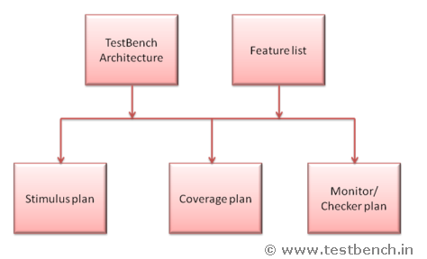
Verification Environment
A detailed TestBench architecture is essential for a robust verification environment. In this section describe the topology, about each component of the TestBench, special techniques that are used, IPs, Reused blocks, new blocks, and guidelines on how to reuse the TestBench components. For example if you think upfront about error injection, configuration, component communication, callbacks etc, you can provide hooks to do those.
System Verilog Verification Flow
Details about each level (block, sub-system, system) and phases (RTL, gate) of verification are mentioned.
Stimulus Generation Plan
The stimulus generation section contains information about different types of transactions, sequences of transactions and various scenarios generated as per the specification.
Each point is associated with
1. Unique name ID
2. Stimulus to be generated for driving into the DUT
3. Configuration/constraints Information
Checker Plan
This section will explain the expected result checking's in the TestBench. This can be done in monitor/checker.
Various fields associated with each of the point are:
1. Checker Unique name
2. Unique Feature ID(Defined in Feature plan)
3. Checker Description
Coverage Plan
The coverage section explains the functional coverage of the features. A functional coverage plan should be built to help implement coverage points in the verification environment. Genarally it would be better if the coverage block is brocken based on the design logical blocks. It will list the various Coverage groups and assertion.
Various fields of the coverage plan section are:
1. Coverage Group
2. Coverage Description
3. Coverage name
4. Unique name ID (Defined in feature plan)
5. Cover point (Items/cross/transition/assertion)
6. Coverage goal
Details Of Reusable Components
This section contains the details of reusable components and the description about their usage.
The Verification Plan is the focal point for defining exactly what needs to be tested, and drives the coverage criteria. Success of a verification project relies heavily on the completeness and accurate implementation of a verification plan. A good plan contains detailed goals using measurable metrics, along with optimal resource usage and realistic schedule estimates. Verification plan gives an opportunity to present and review the strategy for functional verification before the verification engineer have gone into detail to implement it. It also establishes proper communication. Just imagine how it would be working with a multisite project and you have a query for which you have to wait till the next day to see the answer in email and they just call you while you are in sleep. It also gives an idea about the areas that are going to be difficult to verify for taking necessary steps. It is used to determine the progress and completion of the verification phase of verification. Verification Planning should start early with system/architecture evaluation phase. Once the functional spec is given to the verification team, they will start its development.
A verification plan could come in many forms, such as a spreadsheet, a document or a simple text file. Templates are good if continually used in your company as it makes common interface for information, reviewer know where to look for certain information even in a huge document that he wants to know at this moment, because different reviewers want different infomation in different moments.
Generally Verification plan development is divided in two steps: What to verify and How to verify?
Step one: What to Verify?
list of clearly defined features-to-verify. This is called feature extraction phase.
Step two: How to Verify?
After defining what exactly need to be verified, define how to verify them.
Verification Plan Contains The Following:
Overview
Resources, Budget and Schedule
Verification Environment
System Verilog Verification Flow
Feature Extraction
Stimulus Generation Plan
Checker Plan
Coverage Plan
Details of reusable components
Overview
This section contains description of the project, what specification is followed, what languages and methodology are used. Information related to the HW blocks, SW blocks and HW/SW interaction is outlined.
Feature Extraction
This section contains list of all the features to be verified. Generally each feature is associated with
1. Unique Name Id
2. Description
3. Expected result
4. Pointer to the specification
5. priority.
The "Unique name ID" should be descriptive in nature to understand the nature of the feature and should be unique. For example, <module name>_<sub module>_<feature number>_<feature name>
Some points on how extraction the features:
Read the MRD, System Specification, Macro and Micro Hardware Specification.
Go through the designer notes/presentations.
Annotate each line/paragraph specifying a functional item e.g., read/write a register
Annotate each line/paragraph specifying a multiple-functional items e.g., steps required to set and cause an interrupt .
Identify all RTL configurations
Identify interfaces and related protocols across interface.
Identify standards compliance requirements, list corner cases.
Create a list of illegal scenarios to verify.
Create a list of exceptions to verify.
Create a list of operation sequences to verify e.g., interrupt followed by breakpoint etc.
Create a list of things to try and break the machine.
Take advantage of existing plans.
Use points from compliance checklist for standard protocols.
Get information about the Common tests for all chips.
Get review by a number of people, usually very experienced engineers. Better if you get reviewed by Architects, micro Architects, Leads, verification engineers, RTL Designers, software designers, marketing team and other team members.
Resources, Budget And Schedule
This section contains details of man power required and schedule for each phase of the verification. Information about the tools which are used for simulation, debugger and bug tracking are listed.
Verification Environment
A detailed TestBench architecture is essential for a robust verification environment. In this section describe the topology, about each component of the TestBench, special techniques that are used, IPs, Reused blocks, new blocks, and guidelines on how to reuse the TestBench components. For example if you think upfront about error injection, configuration, component communication, callbacks etc, you can provide hooks to do those.
System Verilog Verification Flow
Details about each level (block, sub-system, system) and phases (RTL, gate) of verification are mentioned.
Stimulus Generation Plan
The stimulus generation section contains information about different types of transactions, sequences of transactions and various scenarios generated as per the specification.
Each point is associated with
1. Unique name ID
2. Stimulus to be generated for driving into the DUT
3. Configuration/constraints Information
Checker Plan
This section will explain the expected result checking's in the TestBench. This can be done in monitor/checker.
Various fields associated with each of the point are:
1. Checker Unique name
2. Unique Feature ID(Defined in Feature plan)
3. Checker Description
Coverage Plan
The coverage section explains the functional coverage of the features. A functional coverage plan should be built to help implement coverage points in the verification environment. Genarally it would be better if the coverage block is brocken based on the design logical blocks. It will list the various Coverage groups and assertion.
Various fields of the coverage plan section are:
1. Coverage Group
2. Coverage Description
3. Coverage name
4. Unique name ID (Defined in feature plan)
5. Cover point (Items/cross/transition/assertion)
6. Coverage goal
Details Of Reusable Components
This section contains the details of reusable components and the description about their usage.